This page reports on my design process and preparations for
this
sculpture, which I call Gyrangle.
The
following text and images accumulated over the period of
May-October 2012. Pictures of the Oct 23-25 assembly are
shown
separately here.
1. The Sculpture
Here is a concept sketch for a
sculpture
I am
designing. It is modular, being made of 490 hollow
triangles. Look carefully and you can see that many of the
triangles have a fold in them. There are just these two
geometric
units---flat triangles and triangles with a 109.5 degree fold.
And I
plan to have four colors for each, making a total of eight
types of
part. What is most important to me
is the interesting geometry and the fact that it can be built by
many
people who contribute by each attaching one or two
triangles. And
what's especially interesting is the variety of patterns of
tunnels
that can be seen from various directions:
 The triangles are made of laser-cut steel, with a six inch edge
length.
The total weight is about 120 pounds and the height is about 42
inches. I've named it Gyrangle,
because
it is based on a gyroid
surface but is
made of triangles. (That is a title I made up, not a
standard
mathematical term.)
The triangles are made of laser-cut steel, with a six inch edge
length.
The total weight is about 120 pounds and the height is about 42
inches. I've named it Gyrangle,
because
it is based on a gyroid
surface but is
made of triangles. (That is a title I made up, not a
standard
mathematical term.)
Note that I don't usually show my design ideas like this before completing a sculpture. I like to experiment, and the details of my plans usually continue to evolve up until the last moment. So it is possible I will decide to make a rather different form from what is shown above, while still adhering to the mathematical ideas explained below. One advantage of these triangle modules is that they can be assembled into a wide variety of structures. I will experiment with them after they are fabricated, before the assembly event, and may come up with a final design I like even better.
Note that I don't usually show my design ideas like this before completing a sculpture. I like to experiment, and the details of my plans usually continue to evolve up until the last moment. So it is possible I will decide to make a rather different form from what is shown above, while still adhering to the mathematical ideas explained below. One advantage of these triangle modules is that they can be assembled into a wide variety of structures. I will experiment with them after they are fabricated, before the assembly event, and may come up with a final design I like even better.
2. The Assembly Process
The sculpture will be assembled on
the
National
Mall in Washington D.C. on Oct 23 and 24, 2010. This will
be the
weekend of the USA
Science and Engineering Festival. I will be leading the
assembly
process at the booth of the American
Mathematical
Society. The event is free and open to the public.
Come join us and participate in the construction!
The basic construction units are hollow metal triangles with bent connectors for joining to their neighbors via nuts and bolts. The hole's edge is exactly half the whole edge length. About half the parts are flat and half are partly folded. I will bring these laser-cut metal triangles with appropriate connectors to easily screw them together at the proper dihedral angles. Anyone who is able to use a screwdriver can visit the AMS booth and add a triangle piece to the growing sculpture. The connectors will probably be much like the ones I used here, which worked very well, but with three dihedral angles: planar, tetrahedral, and octahedral.
I have led many previous sculpture barn raisings (see my web pages for examples) but I never can predict exactly about timing. We will have about seven and a half hours on Saturday and again on Sunday for the construction. I hope it will take under two minutes to select and add a piece to the growing sculpture, i.e., at least thirty per hour. So we can build something with roughly 7.5·2·30 = 450 triangles. The design above has 490 parts, so I expect it will take the two days to assemble, but might not be too ambitious if we can get some parallelism going. But we'll see where we actually stand as saturday moves along.
Afterward, the sculpture will be delivered to Towson University to be permanently displayed as a donation by the AMS.
3. The Underlying Mathematical Structure
The underlying mathematical ideas
which
make this sculpture possible are rather intricate, so I made
some
animations to help communicate the geometric concepts. You
don't
need to
understand the following to participate in the sculpture barn
raising,
but reading this
may give some insight into what inspired me about this design
and
what you can look for in it.
The sculpture is based on what is called the (10,3)-a lattice, which is shown above. (To be more precise: the actual lattice extends infinitely in all directions and this is just a manageable cube-shaped chunk of it to display.) The blue spheres are the lattice points. They each have integer coordinates, so this is a subset of a standard cubic lattice, but it is a tricky subset to understand. The green edges connect adjacent vertices; each is of length square-root-of-two. At each lattice point, three green edges meet with an equal angular spacing of 120 degrees. The thin yellow lines are 3-fold rotational axes of the entire structure. They each are parallel to one of four directions---the directions of the long diagonals of a cube. The animation focuses on three important views: looking in the directions of a 4-fold axis, a 3-fold axis, and a 2-fold axis of the underlying cubic lattice.
It is a wonderful fact that we can
wrap
triangles around the lattice as shown above. The hollow
triangles allow you to see some of the lattice inside. A pair of
triangles make a sandwich around each lattice point, but they
point in
opposite directions, like the bases of a triangular antiprism.
The
four families of yellow 3-fold
axes pass orthogonally through the holes of the triangles.
As
there are four families of yellow lines, so the
triangles are in four different parallel families, which are
distinguished
here by differing colors. Notice that the triangles do not share
a full
edge with any other triangle.
 This animation shows how the triangles meet. The blue sphere
here is a
triangle vertex, not a lattice point. Every vertex of every
triangle
has this same configuration of four triangles around to it. It
is a
vertex of two opposite facing triangles and is the midpoint of
two
neighbors' edges. Triangle edges half overlap, yet
(ignoring the hole shown in each triangle) everything seals up
to
make a 2D manifold of triangles. All the triangles are
equivalent in
the structure, i.e., you can rotate the whole infinite structure
to
position any
given triangle in the location of any other given triangle, and
the
entire structure will look unchanged. I used red and yellow to
color
the two sides of the surface, which turns out to be equivalent
to a
gyroid surface.
This animation shows how the triangles meet. The blue sphere
here is a
triangle vertex, not a lattice point. Every vertex of every
triangle
has this same configuration of four triangles around to it. It
is a
vertex of two opposite facing triangles and is the midpoint of
two
neighbors' edges. Triangle edges half overlap, yet
(ignoring the hole shown in each triangle) everything seals up
to
make a 2D manifold of triangles. All the triangles are
equivalent in
the structure, i.e., you can rotate the whole infinite structure
to
position any
given triangle in the location of any other given triangle, and
the
entire structure will look unchanged. I used red and yellow to
color
the two sides of the surface, which turns out to be equivalent
to a
gyroid surface.
In the above image, I have removed
the
lattice to show just the pattern of the triangles, and again
focus on
a 4-fold, 3-fold, and 2-fold direction of the surrounding
cube. The different shapes
of tunnels in different directions are spectacular.
Because you
are mainly seeing the exterior of the cube, it may be difficult
to
realize that in the interior everything seals up nicely.
The
unhappy gaps and sharp corners along the outer boundaries of
this
cube-shaped chunk of the lattice will be addressed below.
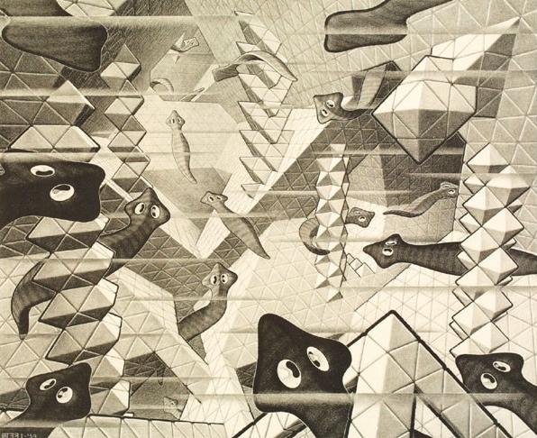
The above animation shows another direction from which one can
come to
understand this structure. Perhaps you know that regular
octahedra and regular tetrahedra can pack space without any gaps
when
put together so each octahedron is surrounded by eight
tetrahedra and
each tetrahedron is surrounded by four octahedra. If you had
magnetic
octahedra and tetrahedra building blocks, you could stick them
together
to make many cool things. M.C. Escher's Planaria
is
all
about
exploring
this
idea.
It
turns
out
that
by
removing
cells
from
the
infinite
"oct-tet"
space
packing,
we
can
make
the
triangle
construction.
The
large
hollow
triangles
of
the
earlier
images
are
now
divided
into four
half-size triangles---one
octahedron face surrounded by three tetrahedra faces. A (10,3)-a
lattice can be
intricately linked with a mirror-image copy of itself, as
illustrated here.
So the
various tunnels in our sculpture have room to hold a
mirror image
copy of the same sculpture!
In this tetrahedron/octahedron derivation of the structure, some odd-shaped polyhedral blobs at the boundaries are the result of our cutting this finite chunk from an infinite pattern. And recall that sharp corners and open gaps were the analogous boundary effects in the earlier triangle-sandwich-around-a-lattice construction. Neither of these consequences is satisfactory to me, but with some work, we can terminate the infinite construction in a very nice manner:
In this tetrahedron/octahedron derivation of the structure, some odd-shaped polyhedral blobs at the boundaries are the result of our cutting this finite chunk from an infinite pattern. And recall that sharp corners and open gaps were the analogous boundary effects in the earlier triangle-sandwich-around-a-lattice construction. Neither of these consequences is satisfactory to me, but with some work, we can terminate the infinite construction in a very nice manner:
The above
chunk was derived by repeatedly pruning all
leaves from the cube-shaped chunk of the lattice, until each
remaining
lattice point has two or three neighbors. It turns
out that by applying this algorithm, the only gaps are adjacent
pairs
of triangles and
we can
partially fold one pair of the sharp triangle corners to close
each
gap. When a triangle is folded, its paired triangle around a
lattice
point (the matching "slice of bread" from one "sandwich") is
also
folded to meet it. So by using modules which are triangles and
bent
triangles, I have the freedom to
choose a volume of any shape, as long as every (10,3)-a lattice
vertex is
of degree at least two. (Of course, there are other constraints,
such as complexity, cost, stability, and engineering strength to
consider when designing a sculpture.) The quasi-randomness in
the
pattern of colors that face the viewer is a nice feature of this
method
that I hadn't expected.
4. An Alternate Design
As an alternate to the tetrahedral
frame
shown at the top of this page, another possible design is this
simpler
head-and-shoulders form, consisting of 446 triangles. The
red
base derives from a cube standing
up on a corner, from which we slice the top and bottom vertex.
Think of
the polyhedron made famous in Durer's
Melancholia, but
shorter. Walking around it, the viewer may be surprised to
observe three of the four hexagonal tunnel directions. The
fourth set
of hexagon tunnels can be seen from directly above, because a
3-fold
axis is vertical. The yellow orb that sits on
it is based on a truncated cube also, but with different
proportions.
 I like the subtle allusion to Durer. And it is
wonderful to realize that
we could also make a mirror image structure which fits in the
exterior
holes that pass through it. I think this would be interesting to
assemble,
but I am still working out all the assembly issues.
I like the subtle allusion to Durer. And it is
wonderful to realize that
we could also make a mirror image structure which fits in the
exterior
holes that pass through it. I think this would be interesting to
assemble,
but I am still working out all the assembly issues.
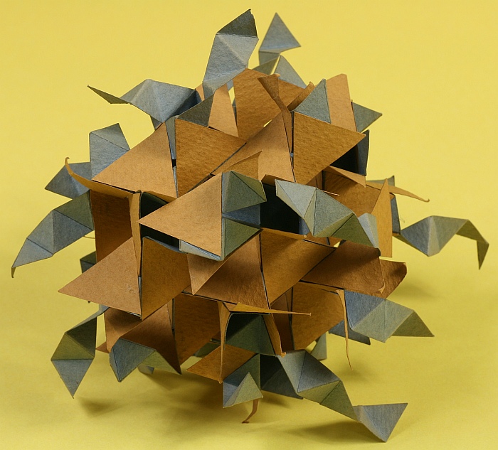
But I don't know anything about the history of this triangle
construction. I discovered it around 1980 and made this paper
model. Only later did I learn about the gyroid surface and
realize that this is a discrete version of it. I assumed
that, as
with the (10,3)-a lattice,
my discovery was a rediscovery and others had known of it
previously,
but I don't know of any previous description of it. Because the
triangles do not meet edge-to-edge, it doesn't fit into the
standard
categories of infinite polyhedra. You can think of the triangles
as
irregular hexagons which then do meet edge-to-edge, but I like
triangles. Or you can divide the triangles into four smaller
triangles
to have two orbits of triangles in the pattern (a3.b.a3.b).
The
closest
relatives
I
know
that
are
described
in
print
are what John H. Conway calls the "propeller-hedron" and the
(6.3.4.3.3) on pp.
326-327 and pp. 338-339 in The
Symmetries
of Things, by Conway, Burgiel and
Goodman-Strauss. Please let me know if you can provide
me with additional references.
Since 1980, this paper model has been sitting in my office and I've thought off and on about making a large sculpture of some kind based it. I am very happy that this commission by the AMS has given me an opportunity to do so. I feel the deep geometric ideas which make this construction possible are very worthy of an artwork for a professional mathematical organization like the AMS, and the modularity is what is needed for a public sculpture barn-raising assembly.
Incidentally, the blue spiral strips in the paper model above provide a continuous set of connectors to join the triangles together. Each blue strip forms a triangulated helix in the direction of a 4-fold axis. They are really quite cool and deserve to be the subject of a future sculpture. Let me know if you want to commission me...
It is quite fun so spin this model around in your hands, looking for all the various shapes of tunnels. In this image, there is a place at the top right where you can see an opening the size of two small (half-edge size) triangles and the points of two triangles above and below the gap. Those points can be folded over to close the gap. An example of a gap covered in this way is shown just left of center, where two of the paper triangles are folded. Inside each of those spaces is a lattice point with just two neighbors instead of three. The third connection would have been in the direction of the gap.
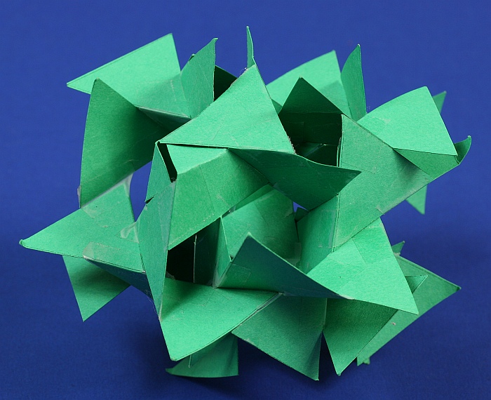
The layout of the triangles in each of the four orientations of planes is that they meet tip-to-tip as shown above. They alternately face inside and outside the enclosed volume, as suggested by the two shades of green. Other families of planes cross this plane at the tetrahedral dihedral angle of roughly 109.5 degrees. Along each of the triangle-boundary lines, analogous lines from two other intersecting planes meet, but those lines are slid over half a triangle edge length relative to these triangles. At each vertex, there are two triangle vertices meeting and two edge midpoints (from one triangle on each side of this plane). Remember to maintain handedness. You can make either of the mirror image equivalents, but be consistent throughout. It all becomes clearer as you build it, but it takes a good number of triangles before you close up around some tunnels.
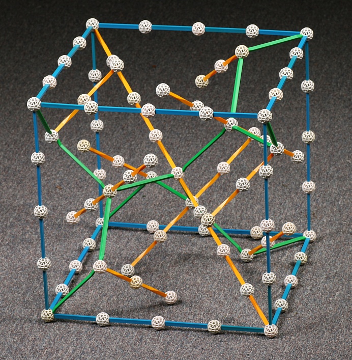
To fully understand the sculpture, you may also want to study
the underlying (10,3)-a lattice. If you have Zometool, it provides
parts with
the appropriate lengths and angles to make a hands-on model. The
green lattice edges and yellow 3-fold axes in the animations
above are
color coded to match the colors of the corresponding Zometool
struts.
The
blue struts here outline the underlying cubic lattice.
Replicating the cube above as many times as you wish allows you
to
create a very informative model of this intricate and beautiful
lattice. Within a 4x4x4 cube, the lattice points to connect are
at
coordinates: (0,0,4), (1,0,3), (2,1,3), (3,1,4), (4,0,4), then
(4,0,0),
(3,1,0), (3,2,1), (4,3,1), (4,4,0), then (0,4,0), (0,3,1),
(1,3,2),
(1,4,3), (0,4,4), then connect (2,2,2) to its three neighbors.
Pairs
separated by a distance of square-root-of-two get connected with
a
green edge.
7. Thinking Bigger
5. History
The (10,3)-a lattice has a long history of independent rediscoveries. It has also been called the Laves graph (of degree three or of girth ten), and the triamond lattice. There is a list of references about it here.Since 1980, this paper model has been sitting in my office and I've thought off and on about making a large sculpture of some kind based it. I am very happy that this commission by the AMS has given me an opportunity to do so. I feel the deep geometric ideas which make this construction possible are very worthy of an artwork for a professional mathematical organization like the AMS, and the modularity is what is needed for a public sculpture barn-raising assembly.
Incidentally, the blue spiral strips in the paper model above provide a continuous set of connectors to join the triangles together. Each blue strip forms a triangulated helix in the direction of a 4-fold axis. They are really quite cool and deserve to be the subject of a future sculpture. Let me know if you want to commission me...
6. Make Your Own Model
A good way to learn about any topic in 3D geometry is to make your own physical models. If you want to understand more about this sculpture, I suggest you make a simple paper model. Cut out a pile of equilateral triangles and tape them together so the edges half overlap like this:It is quite fun so spin this model around in your hands, looking for all the various shapes of tunnels. In this image, there is a place at the top right where you can see an opening the size of two small (half-edge size) triangles and the points of two triangles above and below the gap. Those points can be folded over to close the gap. An example of a gap covered in this way is shown just left of center, where two of the paper triangles are folded. Inside each of those spaces is a lattice point with just two neighbors instead of three. The third connection would have been in the direction of the gap.
The layout of the triangles in each of the four orientations of planes is that they meet tip-to-tip as shown above. They alternately face inside and outside the enclosed volume, as suggested by the two shades of green. Other families of planes cross this plane at the tetrahedral dihedral angle of roughly 109.5 degrees. Along each of the triangle-boundary lines, analogous lines from two other intersecting planes meet, but those lines are slid over half a triangle edge length relative to these triangles. At each vertex, there are two triangle vertices meeting and two edge midpoints (from one triangle on each side of this plane). Remember to maintain handedness. You can make either of the mirror image equivalents, but be consistent throughout. It all becomes clearer as you build it, but it takes a good number of triangles before you close up around some tunnels.
7. Thinking Bigger
Just some wild ideas here,
since the
techniques are very general. If some future venue has
time and
space
for
something much larger, many possibilities could be
considered with
these same modules and geometric concepts. This is a nice archway
that
could be made on a scale for people to walk through.
And as long
as I am fantasizing here: with thousands of triangles, you
might make a giant
truncated
octahedron, which might be confused with a
technicolor deathstar...
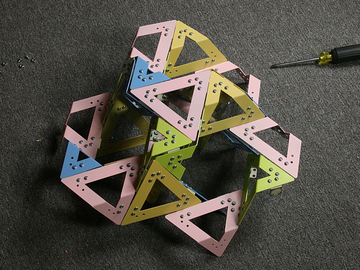
8. Test Parts
I had some test parts laser cut from 16 gauge steel, to
verify
everything fits together properly. These are not yet
painted.
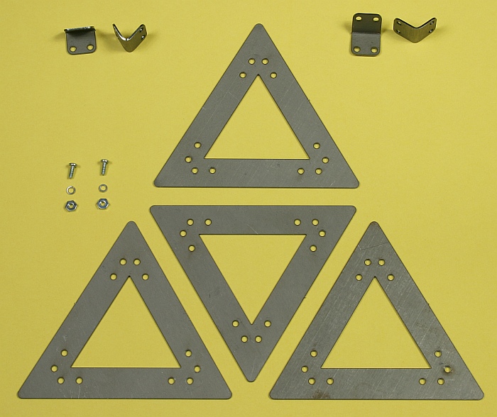
The triangles are 6 inches along the edge. There are two angles for the brackets. The brackets on the top left have the tetrahedral dihedral angle and the ones on the top right have the octahedral dihedral angle.
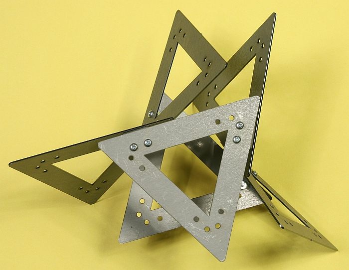
And here is an example of the smallest closed loop one can make. It requires six triangles and six brackets. Everything fits together perfectly and is very solid.
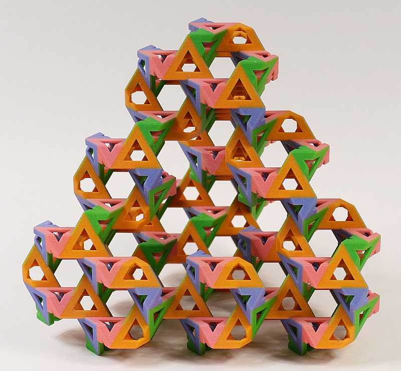
The folks at ZCorp made this beautiful model for me on their color printing machines.
It is 7 inches tall, and shows the structure well. I'll bring it to the barn raising in DC as a guide.
8. Test Parts
I had some test parts laser cut from 16 gauge steel, to
verify
everything fits together properly. These are not yet
painted.The triangles are 6 inches along the edge. There are two angles for the brackets. The brackets on the top left have the tetrahedral dihedral angle and the ones on the top right have the octahedral dihedral angle.
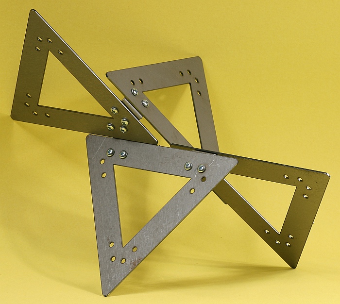
Above is a test-fit of the
generic
vertex, with two coplanar triangles
meeting at their vertices and two others touching at an
edge
midpoint.
Compare this to the rotaing animation above.
And here is an example of the smallest closed loop one can make. It requires six triangles and six brackets. Everything fits together perfectly and is very solid.
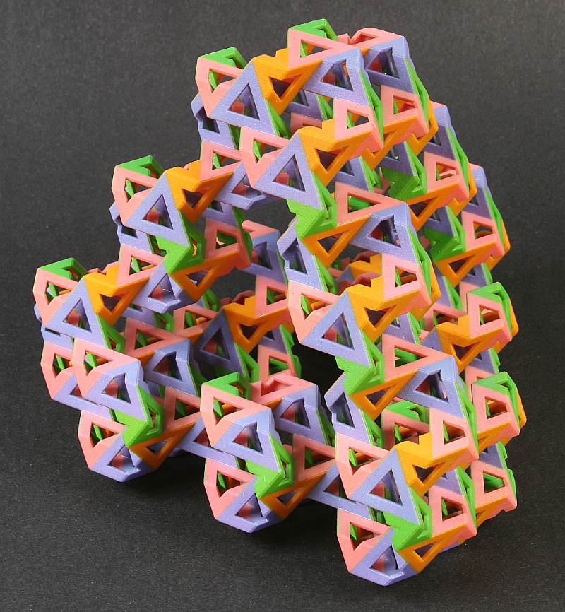
9. ZCorp Model
The folks at ZCorp made this beautiful model for me on their color printing machines.
It is 7 inches tall, and shows the structure well. I'll bring it to the barn raising in DC as a guide.
This view of the model
shows one set
of hexagonal tunnels nicely.
These two shots both show the very top of the sculpture, just moving the camera slightly.
10. Towson University
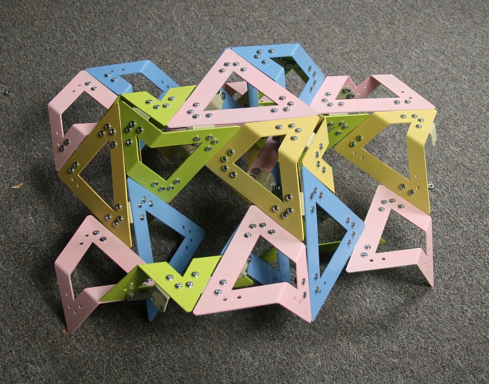
The AMS is donating the sculpture to be permanently displayed at Towson University. We will transport it there sunday evening and install it on monday. I will give a talk about the mathematical ideas underlying it at Towson on Monday, Oct, 25, 4:00, York Building, room 211. You can print out and post this flyer for the talk .11. Test fit
I've now painted all the parts and tried putting some together. It looks really cool! I can't wait to see how it all comes together.These two shots both show the very top of the sculpture, just moving the camera slightly.
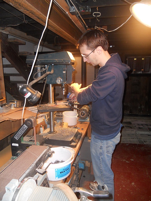
Based on the test fit,
I decided to
drill out holes in some of the brackets to be
slightly oversize.
This provides a bit more play in the assembly,
making it easier to
position the parts. Thank you Colin for
working many hours with
me in my shop to accomplish this: