Zonohedral Dome with 3D-Printed Connectors
At the Construct3D Conference at Georgia Tech
George W. Hart
At the Construct3D
Conference at Georgia Tech, Oct. 5-7, 2018, I led dozens of
conference
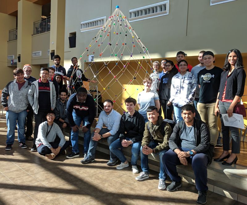
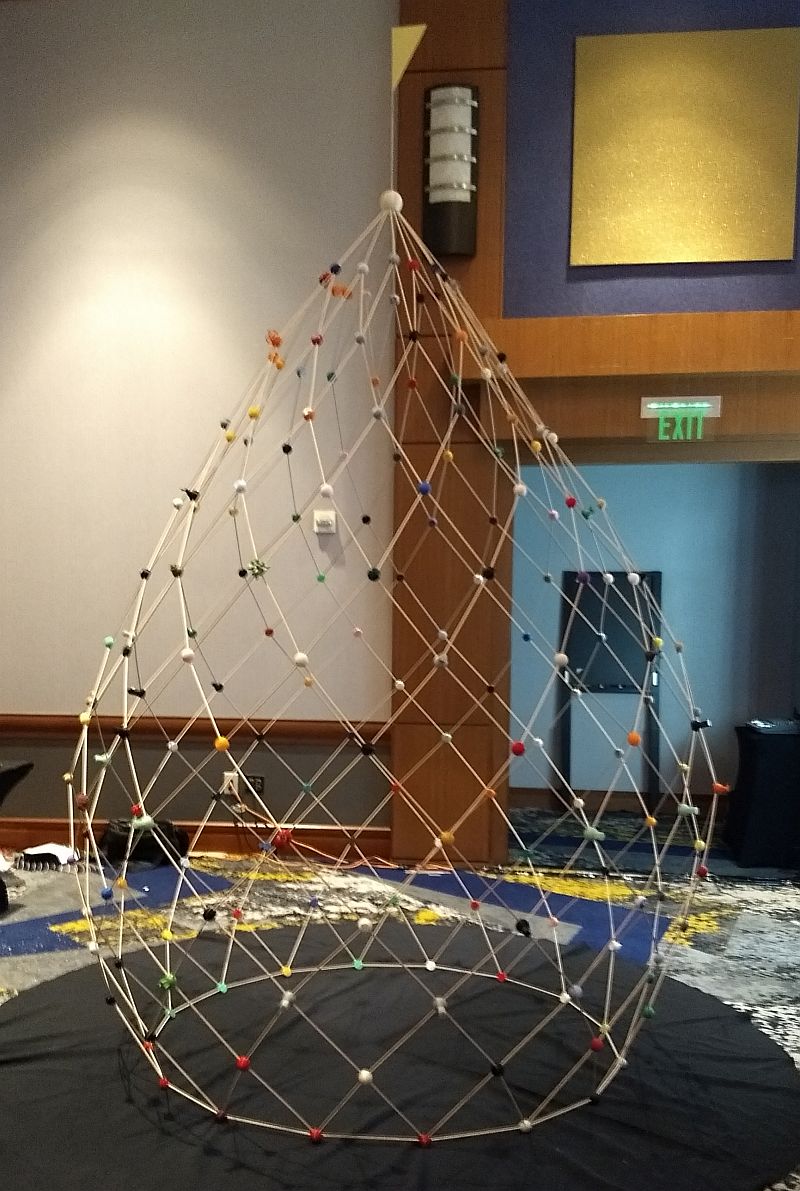
participants in the assembly of a dome I designed, based on the shape of a polar zonohedron.
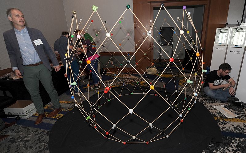
The completed twelve-foot tall construction, made with 193 3D-printed connectors, is shown above.
participants in the assembly of a dome I designed, based on the shape of a polar zonohedron.
The completed twelve-foot tall construction, made with 193 3D-printed connectors, is shown above.
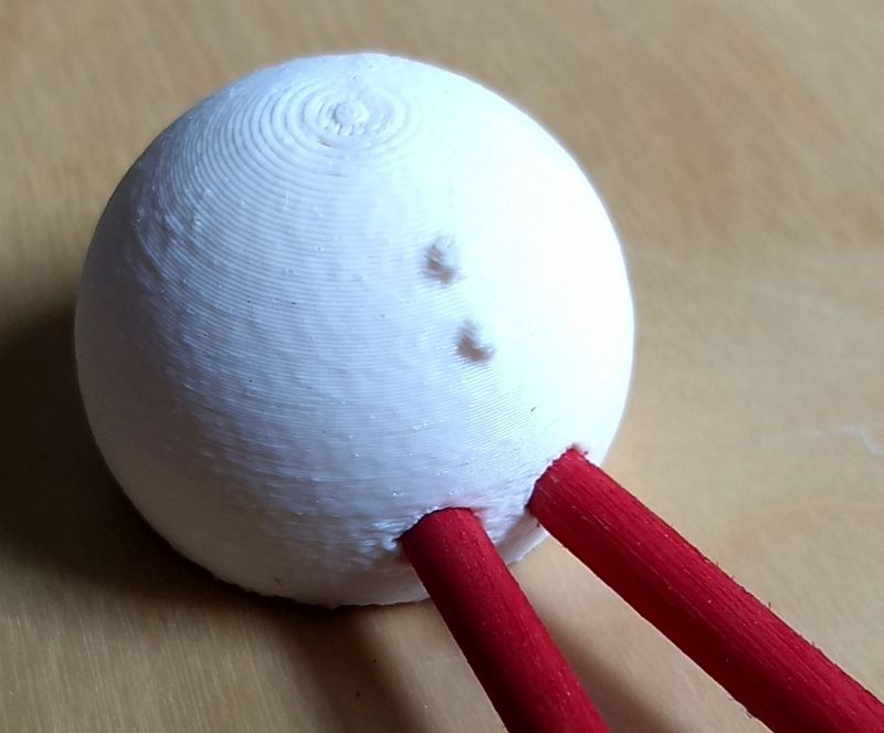
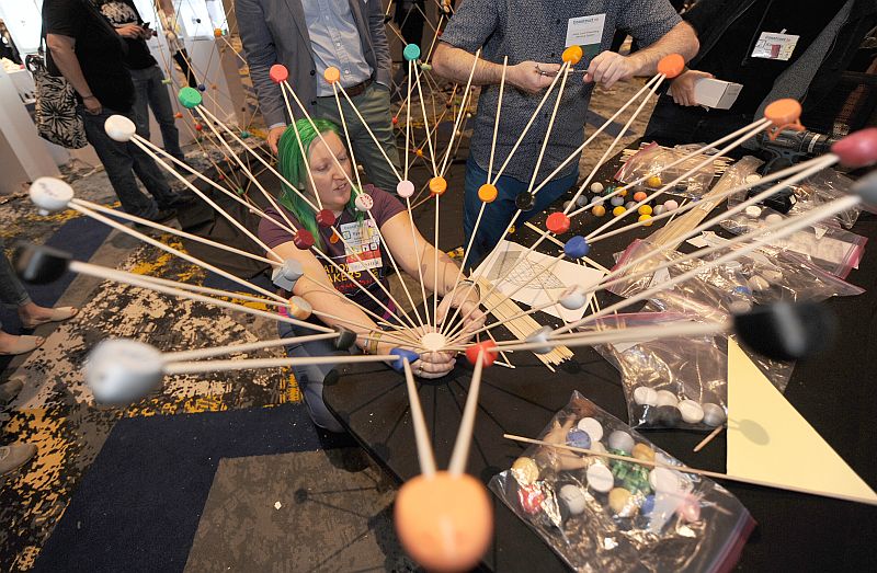
The struts are 3/16 inch diameter wooden
dowels, each one foot long, held together
at the proper angles by inserting them into holes in the plastic connectors.
at the proper angles by inserting them into holes in the plastic connectors.
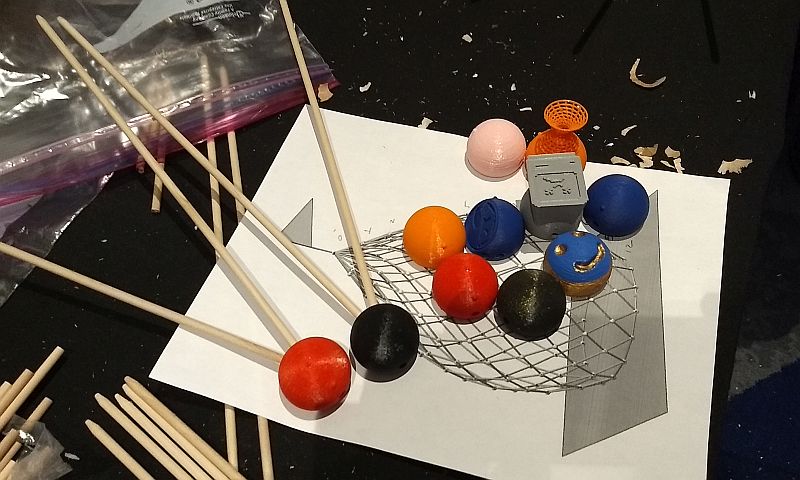
There are ten basic types of connectors, each specifically designed with holes set at
the correct angles for certain positions in the dome. Markings indicate which are which.
They are roughly spherical but have flat side, which aids in orientation during the assembly
and helps them stick to the platform when 3D-printing without support material.
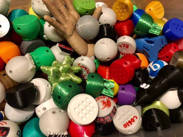
It is a lot of work to make 193 connectors. Many people contributed to the 3D printing through
the website WeTheBuilders, which organizes large multi-part 3D-printed constructions.
Anyone could sign up to download the STL files and build some of the required parts.
You can see above that a pattern of indents in the base of each part was designed to
distinguish which part is which. You can also see that many of the parts were customized.
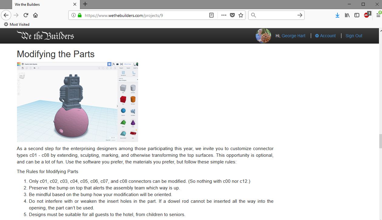
On the WeTheBuilders site, we encouraged people to modify the parts and explained the limits
of what could be changed and what must stay unchanged for the parts to remain functional.
In the weeks before the conference, all the parts (and some spares) were printed by volunteers.
Many were mailed to Atlanta. Others were brought by hand by conference participants,
At the opening of the conference, the Friday evening before the construction,
I gave a plenary talk explaining the project and inviting everyone to participate
in the Saturday assembly for whatever amount of time they wished.
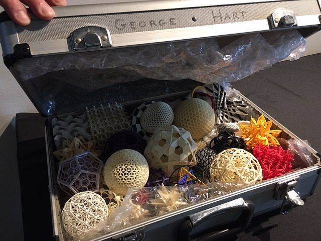
(I also brought a case full of cool 3D-printed models for people to play with, but that's another story...)
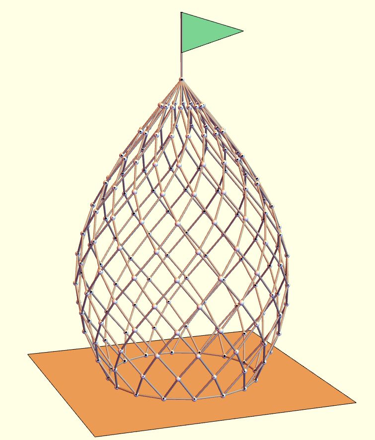
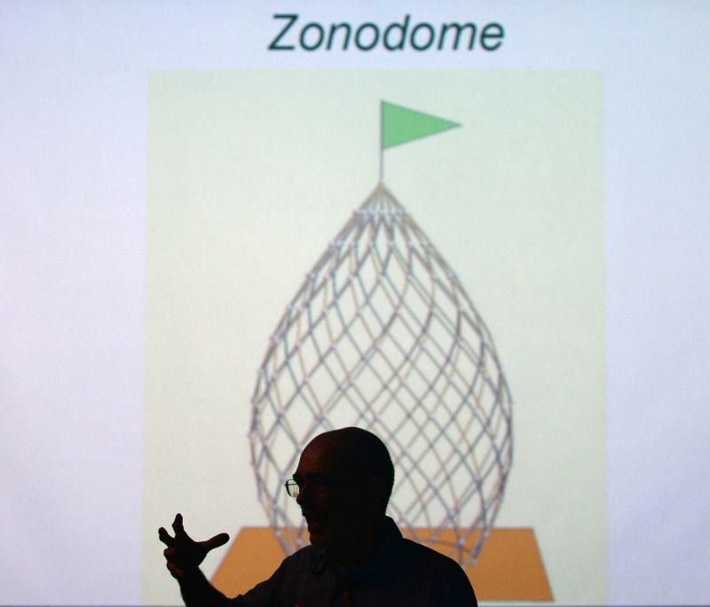
Here's a rendering I made to explain how the Zonodome looks. Using the 193 nodes,
384 struts outline rhombic openings (plus there's one longer strut as a flag mast).
The angles are most acute at the apex and approach right angles at the "equator",
so different connector types are required at each level. "Level 0" is the single
connector at the apex. "Level 8" is the widest. "Level 12" rests on the floor.
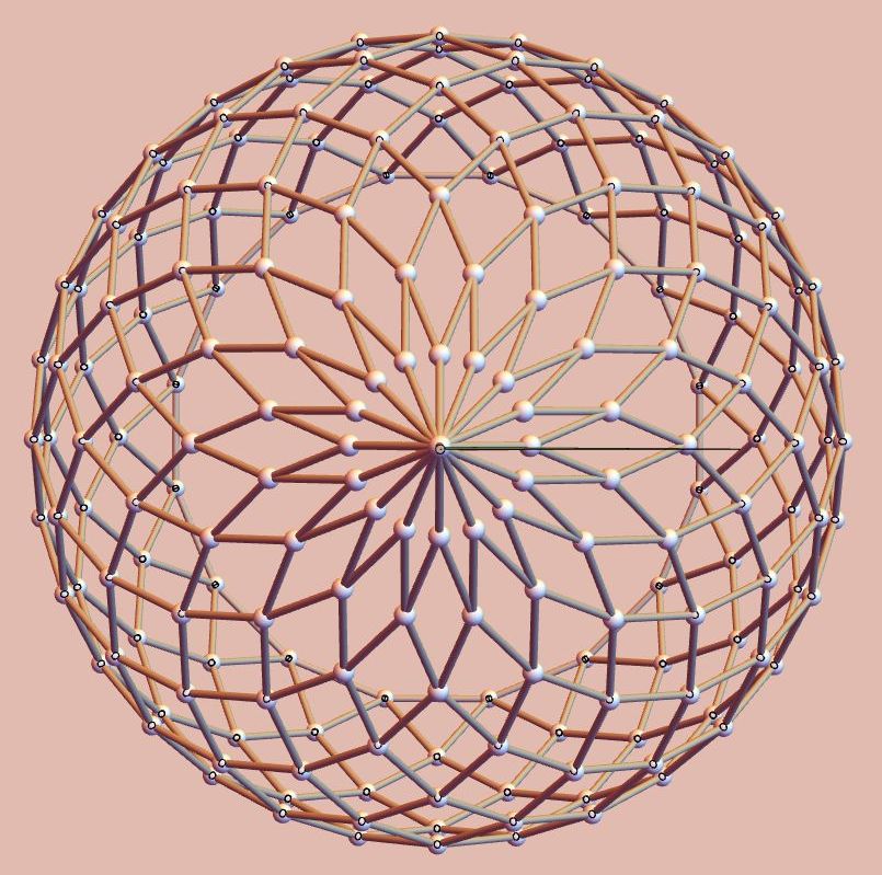
The beauty of the design lies in the spiraling lines, the parallelism of the struts, and the overall 16-fold
symmetry. This top view of the plan makes clear that there are sixteen nodes around at each level.
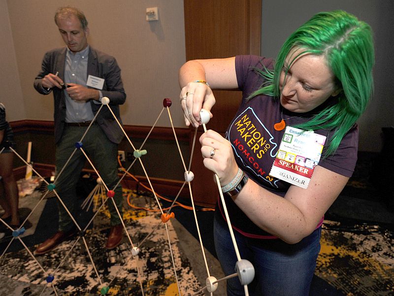
Construction begins on the floor -- level 12 -- then works upwards a level at a time.
It takes some care to ensure the connectors are oriented properly and the dowels are well inserted.
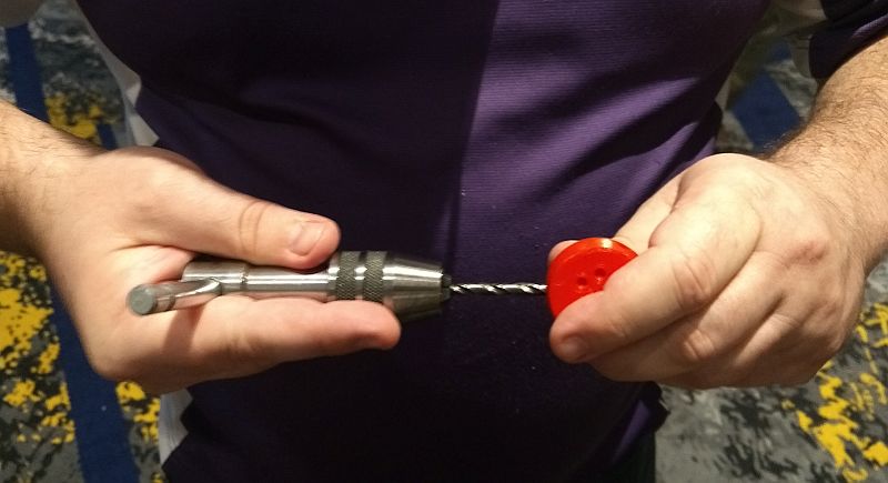
Before inserting the dowels, we reamed out all the holes in the connectors with a drill bit.
Although the STL files for the connectors describe holes exactly 3/16 inch in diameter,
when 3D printing there is always some inaccuracy. The drill bit easily cleans out any
stray material in the holes. It is held here in a tap handle, but one could also use
a power drill if very careful. (Wear gloves to protect your hands!)
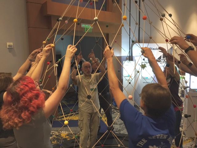
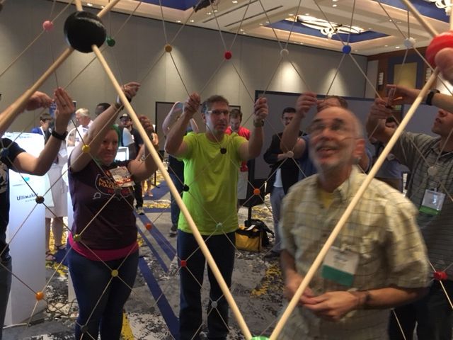
The assembly progressed over a couple of hours. People took turns reaming out the
holes in the connectors while others added parts to the steadily rising structure.
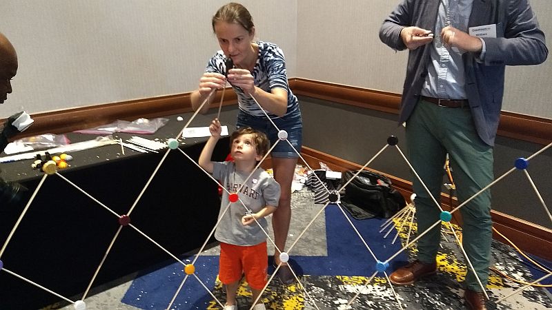
Builders of all ages could participate. And several could work at once all around the circumference.
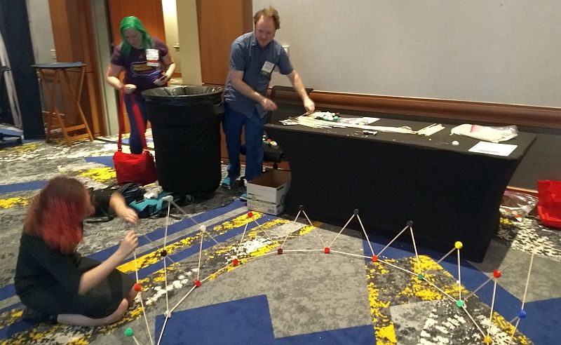
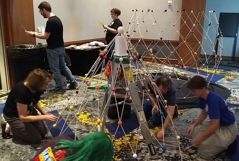
Here it is after working up from level 12 to level 5, about as high as we can comfortably reach.
(Above on the right, you can see our electric pencil sharpening station, to bevel
the ends of the dowels, making it easier to insert them into the connectors.)
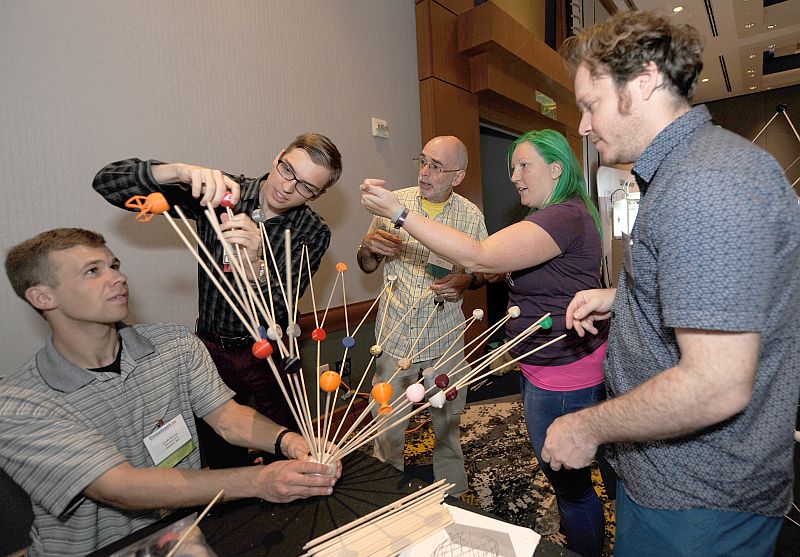
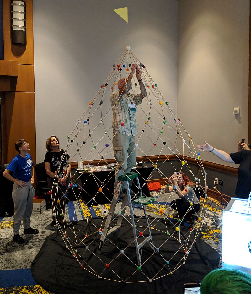
At this point, we started working from the apex, assembling levels 0, 1, 2, ...
On the table here you can see baggies of sorted parts and a triangular paper pennant taped to a dowel for the top.
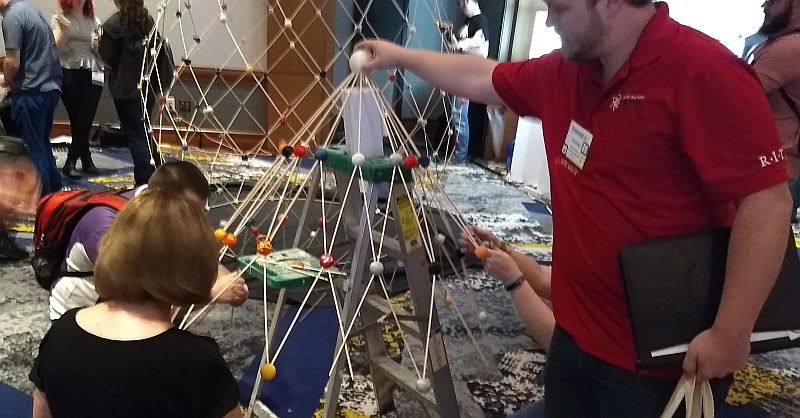
We rested the top on a step ladder and started working downward on level 3.
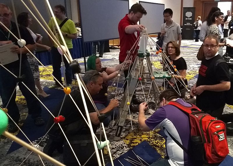
Again, it works out nicely that several people can build at the same time on all sides.
The height of the ladder plus a box conveniently allowed us to work down from level 0 to level 4
and be just above the floor.
Next, with the help of many hands, we lifted up the top and carried it over to the base.
I had climbed inside, to help pass one edge of the top over the open center.
After aligning everything, it was easy for everyone to make the many connections all around.
Something near the apex had jostled loose, so I climbed the ladder to go up and fix it.
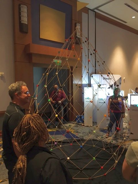
The completed Zonodome remained on display in the exhibition room for the remainder
of the conference then was taken apart to be rebuilt again at future events...
Thank you to everyone who participated in the assembly and to everyone who contributed by 3D-printing the parts. And an extra big thank you goes to Matt Griffin and Laura Taalman, who participated in many aspects of the conception and organization of this project.
Make Your Own Copy of the Zonodome
Everyone is very welcome to replicate this design and even modify it as they like. The main steps are that you will need to print the connectors, order dowels, clean the holes in the connectors, and organize people at the assembly event. Optionally, you can use my software and adjust the parameters to make STL files for the connectors to make a dome with customized size, shape, and/or complexity. But first understand the specifics of this design. Here are detailed instructions:1) Print the connectors. This zip file contains the ten STL files we used for the construction in Atlanta. (To ensure there is no units issue with inchs/cm/mm, check that connectors 1-8 and 12 are 1.5 inches in diameter, roughly 4 cm. Connector 0 is twice that diameter.) Before the assembly event, you need to print (at least) one of level 0 (the apex); 16 each of levels 1-4; 32 each of levels 5-7; and 16 each of levels 8 and 12. (There is no file for levels 9-11 as they have the same angles as levels 5-7.) Make some extra parts as spares. We found that it worked well to set our 3D printers to use 20% infill and three outer layers, with no supports. This makes the parts strong and light and leaves the holes mostly clear. Having three outer layers gives enough material that you can clean the holes without risk of going through the walls. Parts made of ABS plastic are easier to clean than parts made of PLA, because ABS plastic is softer, but both plastics worked for us. Before making all the parts, make a few test parts and be sure you can do the cleaning step well enough to insert your dowels securely.
2) Order dowels. You need 400 dowels that serve as struts. For the construction in Atlanta, we ordered 400 pre-cut hardwood dowels 3/16 inch in diameter and one foot long. If you prefer, it may be less expensive (but more work) to order longer lengths and cut them yourself. The dowels do not need to be one foot long; they could be as short as six inches long to make a half-scale dome or anything in between as long as they are all the same. (I don't recommend going shorter than six inches because if they were shorter, I expect there would be some difficulties during assembly, as they need to flex slightly.)
3) Clean the connector holes. The holes in the connectors will not be super-accurate, because 3D printing is not precise. We need to be able to insert the dowels into the holes with a comfortable friction fit. When you order manufactured wood dowels, they are generally nicely round and of consistent size, but the diameter may not be exactly what is advertised and will vary slightly over time with humidity. You will need to clean out each hole in each connector so your dowels fit in to a depth of 1/2 inch. This can be done by hand with a 3/16 inch diameter drill bit inserted into a tap handle, gently turning it by hand. Or you could use a drill set at low speed, but be cautious. Be sure to wear a glove on the hand holding the part. Don't push in to the end of the hole to make it deeper; you are just cleaning its sides. You may find that a 3/16 bit still leaves the holes a hair too tight for your 3/16 dowels, in which case try a slightly larger size drill bit, e.g., 7/32 inch.
3b) Optionally prepare dowels. We stuck each end of each dowel into an electric pencil sharpener for a second, to bevel the ends slightly. This made it easier to insert the dowels into the holes. But it should not be necessary if your holes are cleaned to the right diameter and the dowel ends are cut cleanly. Also, the sixteen dowels that make a horizontal circle along the floor may need to be cut to a custom length. For the construction above, it worked fine to use one-foot dowels everywhere, but if you customize the dome as described below, the dowels along the floor might be a significantly different length from all the others.
4) Assemble. Follow the plan indicated by the photos above. Sort the connectors. Start at the bottom ring (level 12) and work upward towards the apex (level 0). The flat side of each connector faces the interior. Level 12 connectors do not have a bump for vertical, but it is easy to see which two holes are almost directly opposite each other, and so make the ring along the floor. For levels 11, 10, and 9, use parts 5, 6, and 7, respectively, but with the "verticality bump" facing downward. Finish each level and check the bumps to ensure all connectors are facing the correct direction before moving on to the next level. From level 8 up to the apex, the bump faces upwards. At each step, check the dowels are fully inserted. We built up to level 5, which was at adult head height, then built levels 0 to 4 as a separate unit to be added on top as a final step, but you may find that a different variation on that idea works better for you.
Optional Customization
If you would like to modify the design, you can adjust any of the parameters that affect its size, shape, and complexity. You are welcome to use my Mathematica program and tweak it as you like. If you understand the generic steps described above, the comments in the code should give sufficient guidance for anyone familiar with Mathematica to change the variables they wish and generate a new set of STL files for your custom connectors.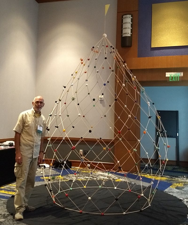
The final result is quite impressive. If you make one, please let me know.
Many photos on this page were taken and sent to me by others.
Thank you to Laura Taalman, Adam Starbuck, and the conference photographer.
Addendum: One month later, another
zonodome was made from these instructions by students
at Georgia State University, Perimeter College, led by Sahithya Reddivari and John Weber.
at Georgia State University, Perimeter College, led by Sahithya Reddivari and John Weber.